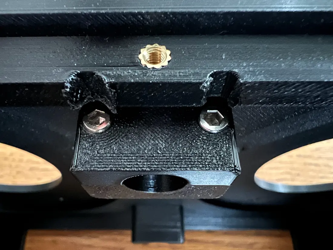
From printing to designing.
A belt tensioner made for this robot. By July, the project was drawing its own parts.
 Szarik
An open quadruped robot
Meet Szarik. A robot to build, understand
and discover the world with.
A hands-on project in development. Build cost and time are still being established.
For curious makers comfortable learning mechanics, electronics and code.
Small robot. Big learning curve.
If you can write software but have never made a motor move, this is a place to start. Szarik connects printed parts, electronics and code in one project you can take apart.
The hero is a rendered motion and conversation demo. Physical performance remains work in progress.
From the workbench
Before the renders came copper wire, printed parts and plenty of things that didn’t fit. A few moments from the build diary.
A belt tensioner made for this robot. By July, the project was drawing its own parts.
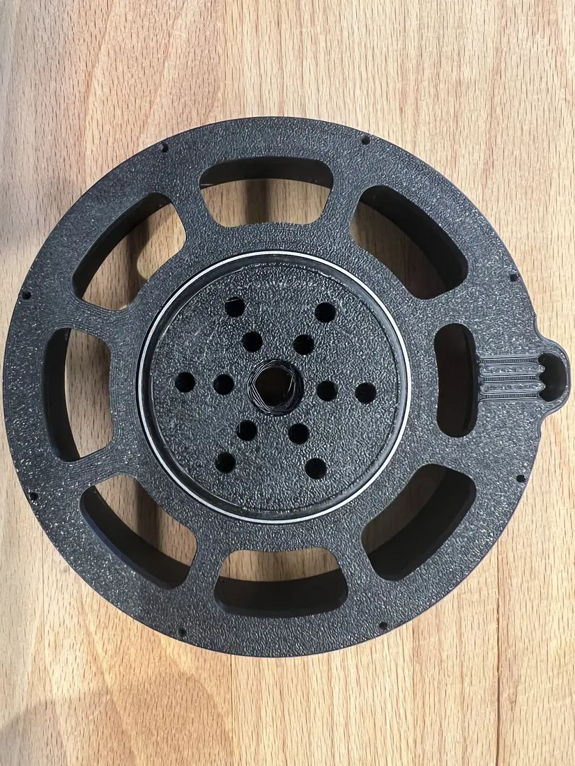
Consistent resistance readings—and a rotor that still rubbed slightly. The difficult bits are part of the story.
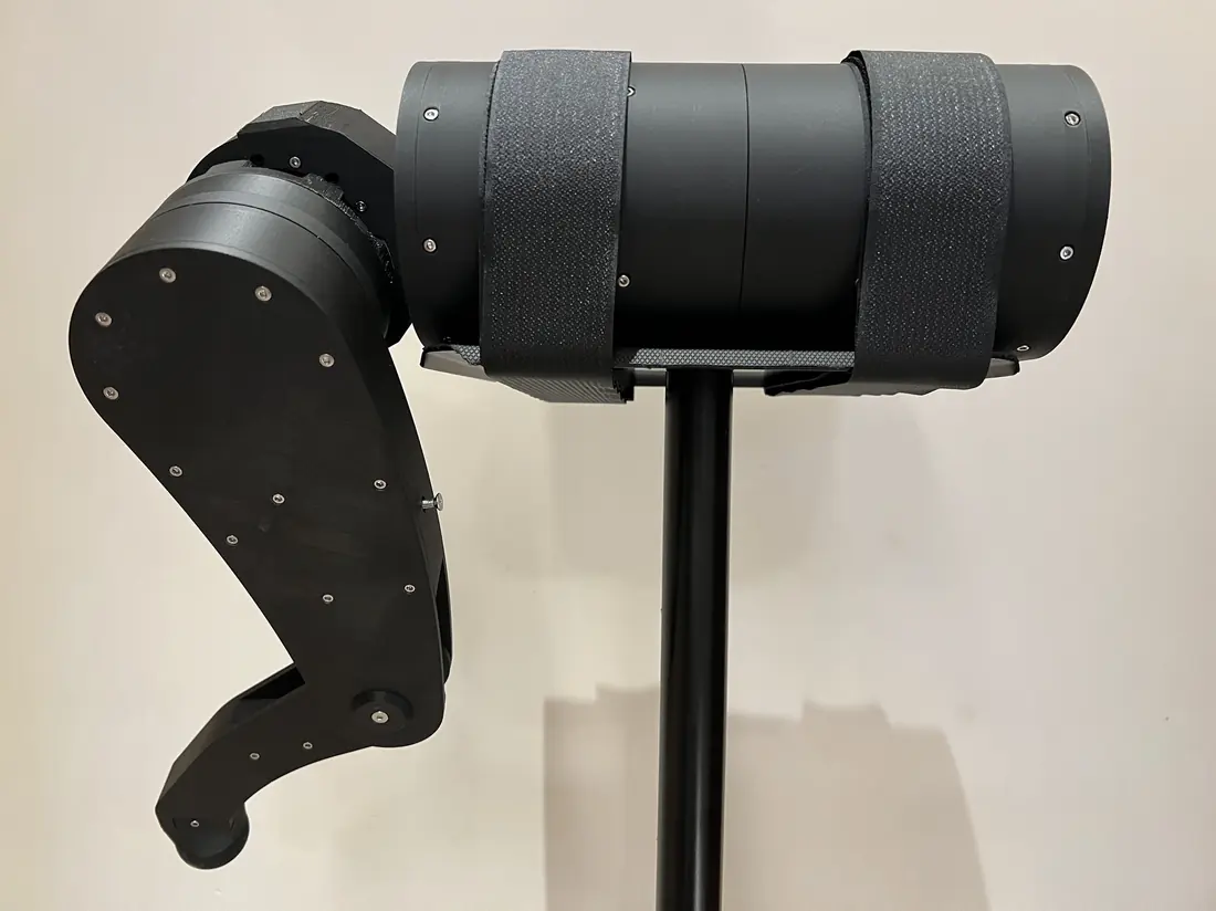
On a stand, with the feet clear of the floor. A way to learn one joint at a time.
Inside every joint
Twelve actuators make the robot move. Start with one: a magnetic motor, a planetary gearbox and parts you can print yourself.
The Szarik actuator
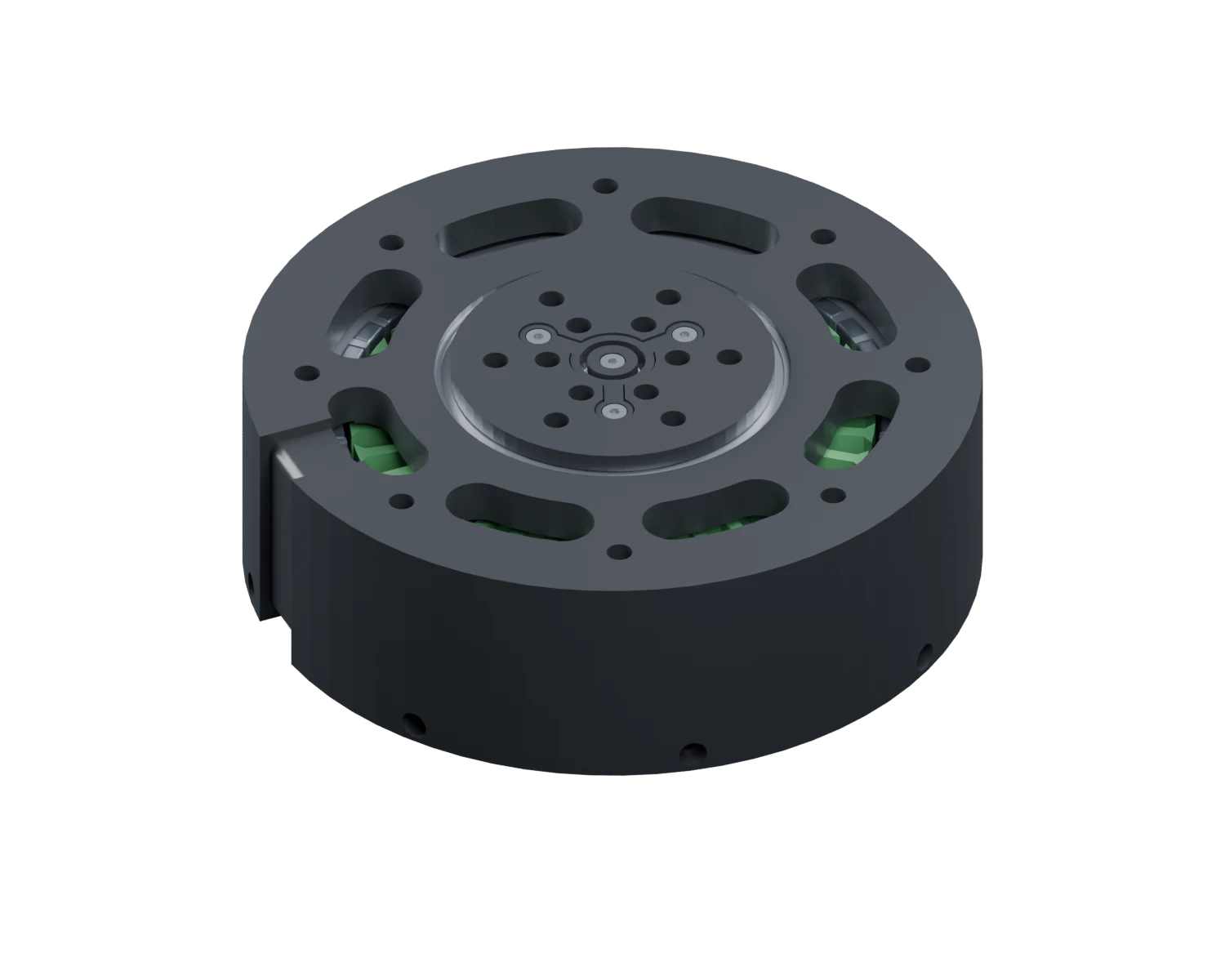
Printed mechanics. Real metal hardware.
Six motor turns.
One output turn.
 42
Alternating north and south.
A shared job
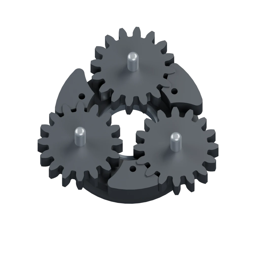
The planet gears travel around the sun gear, inside a fixed ring.
Reference assembly, counting every magnet, screw and insert separately. Electronics and wiring are additional.
Reference mechanical assembly. The wound stator counts as one purchased assembly. Electronics, cables, connectors and robot mounting bolts are additional; later revisions can change the total. Four cover screws have provisional specifications.
Estimated printing time for one actuator, across three plates.
Reference print package 827, sliced for a Bambu Lab H2S with a 0.4 mm nozzle and PETG Basic. Total estimated time: 16 h 8 min 26 s. Individual parts use their saved print settings. Assembly, cooling, support removal and reprints take additional time.
PETG for the printed parts and supports, from the same sliced package.
The three plates use an estimated 238.97 g, 6.41 g and 9.94 g: 255.32 g in total, including supports. This is material consumption, not the weight of the assembled actuator. Complete actuator weight still needs a scale measurement.
From the outside in
A simplified CAD view of the assembled actuator.
Design facts, not rated performance. Torque, efficiency and thermal limits still need measurement.
Make something you can understand
A robot brings the whole stack together. Follow one question from the workbench all the way to the code.
Printed housings and gears meet bearings, magnets, copper and fasteners. Learn why a part that looks right in CAD can still need another print.
Explore the actuator →Each joint has its own ERAD 2.1 driver and magnetic encoder. A spine board joins the twelve joints to the Raspberry Pi.
See the architecture →Rust handles the core control logic. Python drives experiments and simulation. The operator console makes the state visible.
Meet the software →See what the software sees
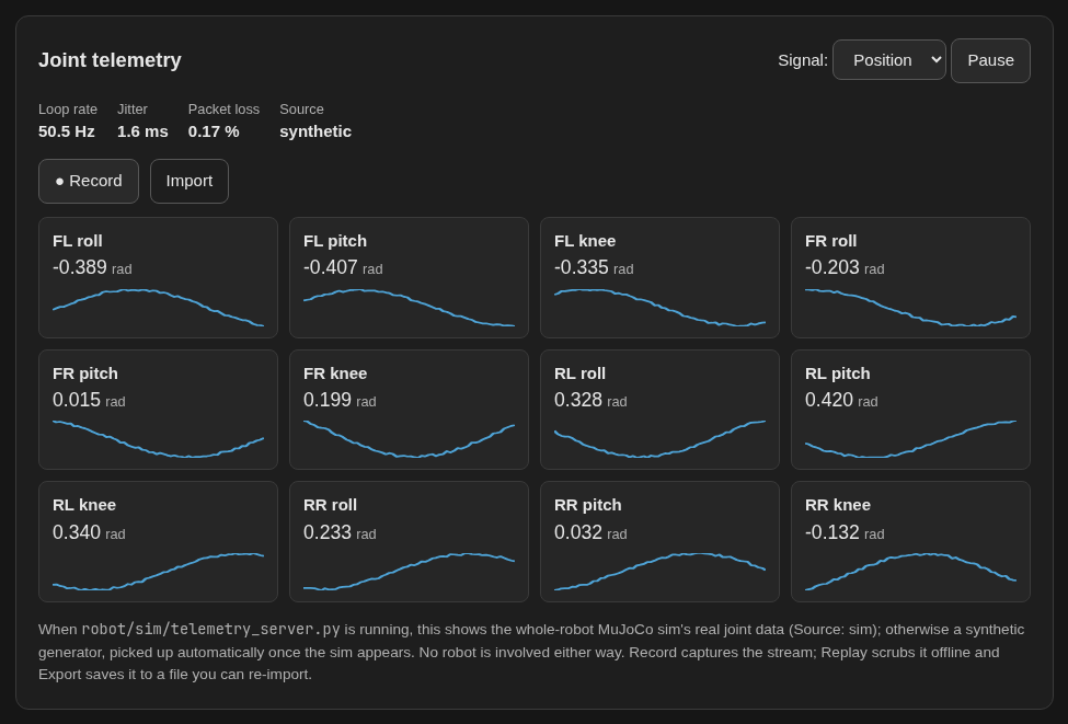
The operator console shows the robot’s state, telemetry and configuration. It’s one more way to turn “why did it do that?” into something you can investigate.
Screenshots from the project’s operator console. This website does not connect to or control a robot.
Curiosity, encouraged
No robotics background required to start reading. Bring your programming experience—and a willingness to meet a few new ideas.
A gearbox trades rotational speed for turning force, called torque. Here, the motor turns six times for one output turn. The three planet gears share the load as they travel around the central sun gear, inside the fixed ring.
An encoder reads the rotor’s angle. This actuator uses a 14-bit magnetic sensor: 16,384 counts across a full turn. That describes resolution—how finely it reports position—not a guarantee of accuracy under load.
Simulation lets you try control ideas against a model before working with a physical machine. Szarik uses MuJoCo. A useful simulated motion is a starting point; contact, friction and real mechanical tolerances still have to be checked on hardware.
Work in progress · 5 November 2026
The complete build cost and repeatable build time are still open. Actuator performance needs bench measurements. The hero shows a scripted rendered demonstration, not recorded physical walking or live recognition.